Tianyixing Electric Heating Equipment Co., Ltd
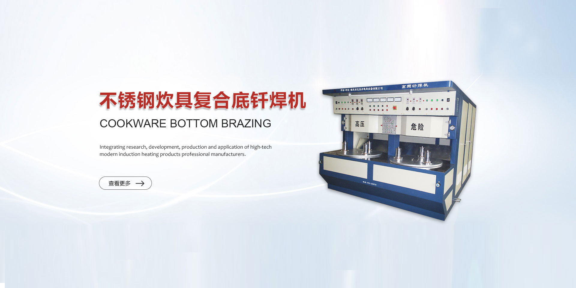
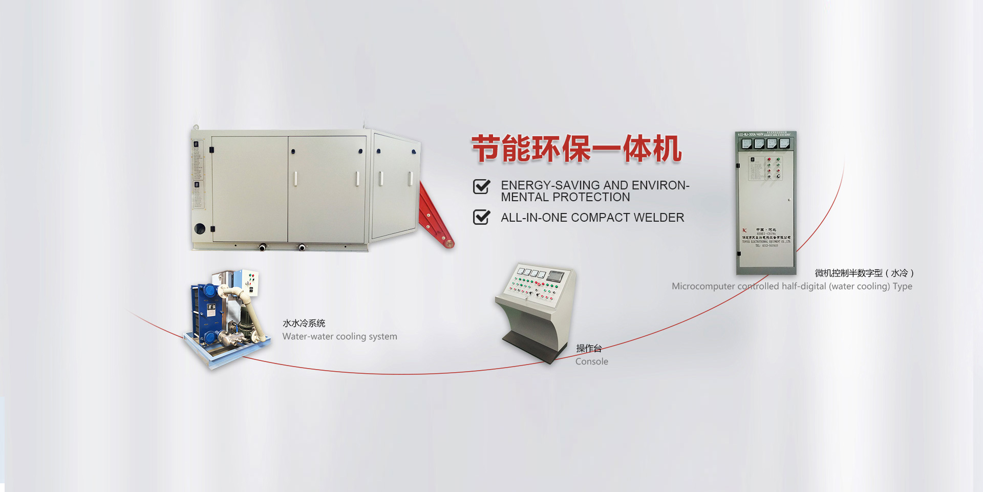
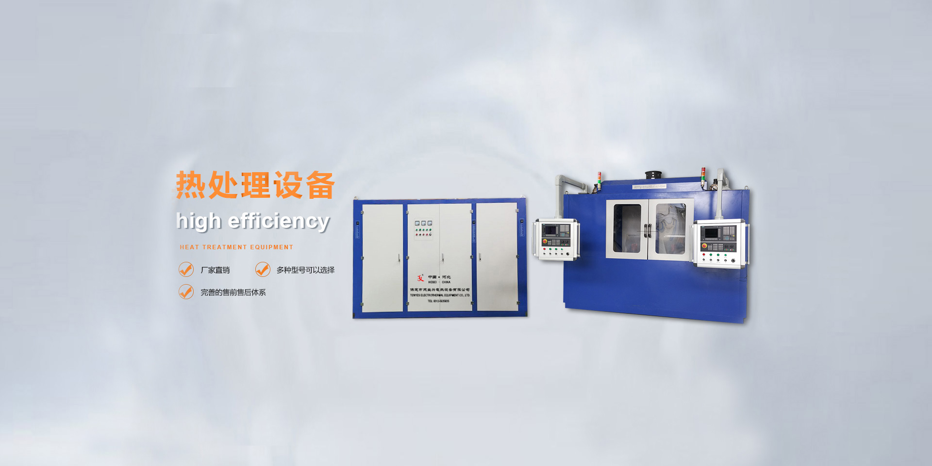
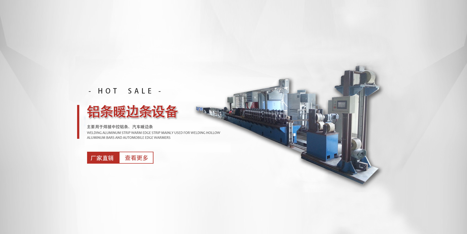
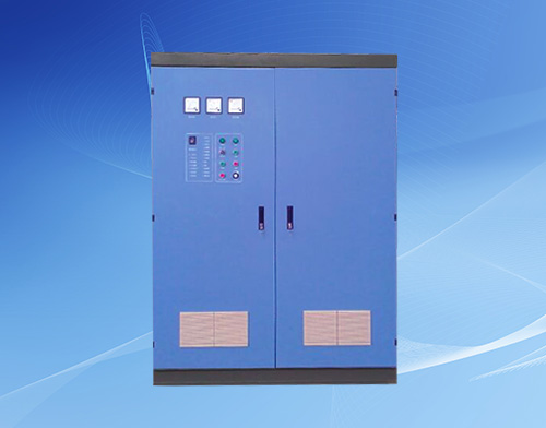
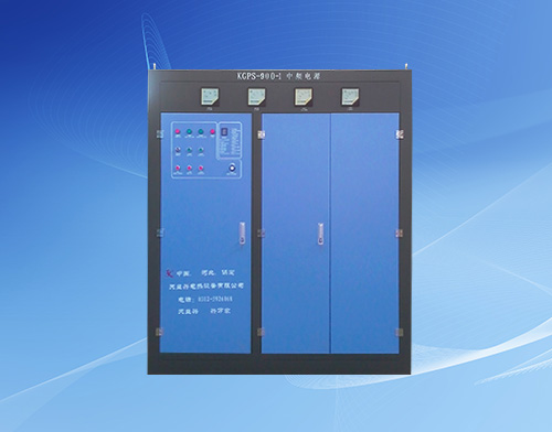
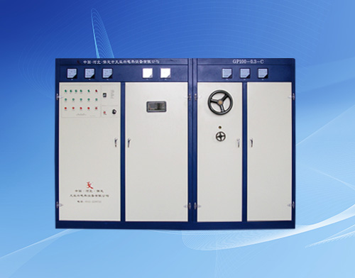
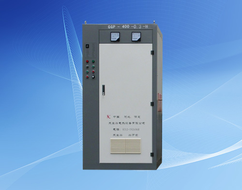
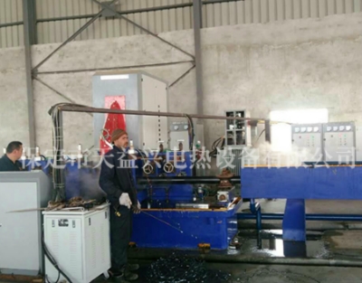
Our company was restructured in 2002 based on the Baoding Tianyi Electric Heating Technology Research Institute established in 1999. It is a business entity that integrates research and development, production, technology, and service, mainly producing induction heating equipment such as high-frequency, ultra audio, and intermediate frequency. Since its establishment, we have successfully developed multiple series and varieties of products. All products are controlled by microcomputers. The product is applied in the fields of welded pipes, brazing, melting (casting), forging, petrochemicals, tableware, and various metal heat treatments (quenching, annealing, tempering), meeting the requirements of induction heating processes such as steel pipe welds, metal heat treatment, metal melting, welding, brazing, hot assembly, etc. It has become the main electrical control equipment for high-strength pipe piles, PC steel bars, aluminum-plastic pipes, wires and cables, hot-rolled, cold-rolled and other production lines. The products are sold to various regions, with some products exported to Southeast Asia, Western Europe and other countries.
More