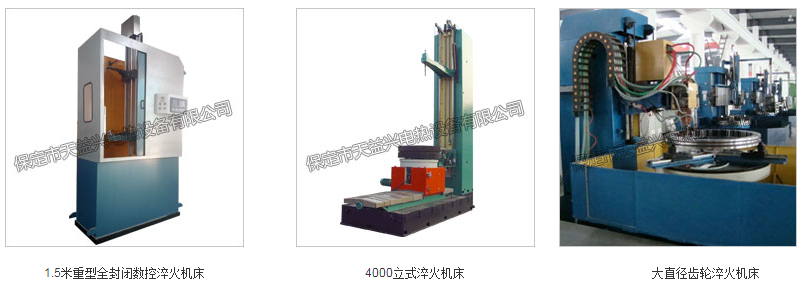
This machine tool is mainly suitable for induction quenching of various types of shafts, discs, and irregular parts.
The machine tool adopts a CNC system to control the quenching speed and position, which can meet the quenching process requirements of the workpiece.
The main characteristics of machine tools:
1. Adopting a CNC (PLC) system for easy operation and intuitive display, multiple heat treatment process programs can be developed and stored according to the different process requirements of the workpiece.
2. The control system reserves quenching heating and cooling water control interfaces, which can fully control the heating and cooling process of the workpiece according to process requirements.
3. The workpiece rotation adopts frequency conversion speed regulation, and the mechanical main lifting transmission adopts AC servo drive, with uniform and accurate feed rate and stable quenching quality.
4. The bed body adopts a steel plate welding structure and undergoes overall stress relief treatment.
5. The key components of the machine tool are all made of anti-corrosion and anti magnetic materials or treated with rust prevention.
6. The quenching methods of this machine tool include continuous heating spray quenching, segmented heating spray quenching, and one-time heating spray quenching.

Solid state high-frequency power supply is designed for continuous operation. The entire equipment is equipped with an STC microcontroller system to achieve comprehensive interlocking control and fault diagnosis functions, and the operating status of the equipment is monitored through digital display. The following is a brief description of the structure and performance of each component:
1. High power factor rectifier cabinet
① The rectifier cabinet adopts PWM switching power supply to improve the power factor of the equipment, and the DC side uses flat wave reactance as a filter to meet the working requirements of the inverter (current type inverter), in order to reduce the output voltage ripple of the equipment and improve the ripple coefficient index.
② The ripple coefficient of the entire machine output is not greater than 1%, ensuring the melting quality. Because there is a magnetic core transformer as the secondary power source isolation, and PWM switching power supply and flat wave reactance as filters are used for rectification, the interference of harmonic components in the power grid on the equipment is avoided.
2. Inverter output cabinet
① Provide the power supply required for high-frequency quenching, and the main power device adopts the American IR company's IRFP460 and IXYS company's DSEI60-06A fast recovery diode to form a current type inverter.
② The output power of the single-layer power module is 50KW, and the whole machine adopts multi-layer power modules in parallel. The rated operating frequency is 400KHZ. The same power modules have interchangeability. This power module can reliably operate at 600KHZ, making it very easy to operate at 400KHZ.
3. The working principle of solid-state high-frequency equipment
Solid state high-frequency power supply is actually a low voltage, high current, AC-DC-AC variable frequency power supply. It rectifies three-phase 380V, 50HZ AC and then inverts it into a single-phase high-frequency AC power supply. The circuit structure is simple, and the main circuit rectifier part is a commonly used thyristor three-phase fully controlled bridge rectifier circuit. PWM switching power supply is used to improve the power factor of the equipment, and the inverter part uses MOSFET field-effect transistors. The midpoint lines of MA+, MA - and MB+, MB - and MB+, MB - are exactly like E-shaped, so we call them E-type bridges.
There are only two printed circuit boards for trigger control, one is a thyristor three-phase full bridge control trigger board, and the other is an inverter control board.
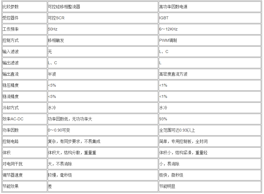
3.1 Comparison between thyristor power supply and high power factor power supply

3.2 Principle and composition of high power factor power supply system
3.2.1 Working principle of Buck voltage reducing chopper
When switch S is turned on, the current flows along circuit 1, causing an increase in the current in L and energy storage, providing power to capacitor C and the load. During the disconnection of S, due to the current in inductor L not being interrupted, the inductor current continues to release energy storage along circuit 2. At this time, the diode takes on the freewheeling effect, and the current decreases with the decrease of inductor energy until the next switch S is turned on. This switching operation is repeated to achieve output voltage and current balance. Controlling the on/off time ratio of switching device S can achieve the effect of controlling the output voltage. In practical applications, switching device S uses high-power semiconductor devices such as IGBT or MOSFET to perform fast on/off control; Buck circuit is a type of step-down circuit, where the output voltage is always lower than the input voltage. Its advantage is that it has a simple structure and can smoothly adjust the output voltage from 0V. The output voltage meets the following requirements:
Vo=(ton/T)×Vi=d×Vi
Among them, ton represents chopping pulse width, T represents chopping period, and d represents duty cycle
3.2.2 PWM control technology
The meaning of PWM is "pulse width modulation", which means continuously adjusting the pulse width of a signal at a certain frequency, driving the switching device, and changing the average value of the output voltage or current pulse wave. As for the Buck chopper mentioned earlier, by allowing the switching device S to receive PWM signal control, the output voltage can operate at the required quantity value according to the system control instructions.
Buck chopper switching frequency
F=1/T f - frequency, T period
In theory, the higher the f, the better. Using smaller LC parameters can achieve better filtering effects. The operating frequency of low-power switching power supplies often reaches hundreds of kilohertz or even higher, which can greatly reduce the size and cost of filters. However, the switching frequency of high-power devices is limited. Excessive switching frequency can increase switching losses, leading to thermal damage to the switching devices. Usually, the switching frequency of IGBT devices can only reach a few kHz to several tens of kHz.
3.2.3. The equipment adopts a step-down chopper working principle and is equipped with multiple protections such as overcurrent, overload, overheating, and short circuit to ensure reliable operation of the equipment. The process structure adopts a rack type overall design, using Infineon IGBT switching devices, Epcos electrolytic capacitors, and high-performance imported chips for control. It has the characteristics of precise calculation and small temperature drift, achieving high stability of DC voltage output control.
3.3 Technical parameters of high power factor power supply:
Output ripple ≤ 0.3% (effective value)
Power efficiency ≥ 93% AC-DC
Power factor ≥ 0.92 (actual test)
Load static adjustment rate ≤ 0.1% V FSC (0-100% I FSC)
Load dynamic adjustment rate ≤ 0.5% V FSC
Automatically set slope for 4S (adjustable for 0.5-30S)
Fault interlocking protection time ≤ 10 μ S
4. Some notable features of the fourth generation solid-state high-frequency power supply
4.1 Simple circuit and convenient installation
After canceling the step-down transformer, the connection between the rectifier and transformer is saved, and there are less than ten control wires between the rectifier cabinet and the inverter cabinet, which is convenient for configuration. There are also few connections between the rectifier power supply and the control panel.
4.2 Complete protection and easy maintenance
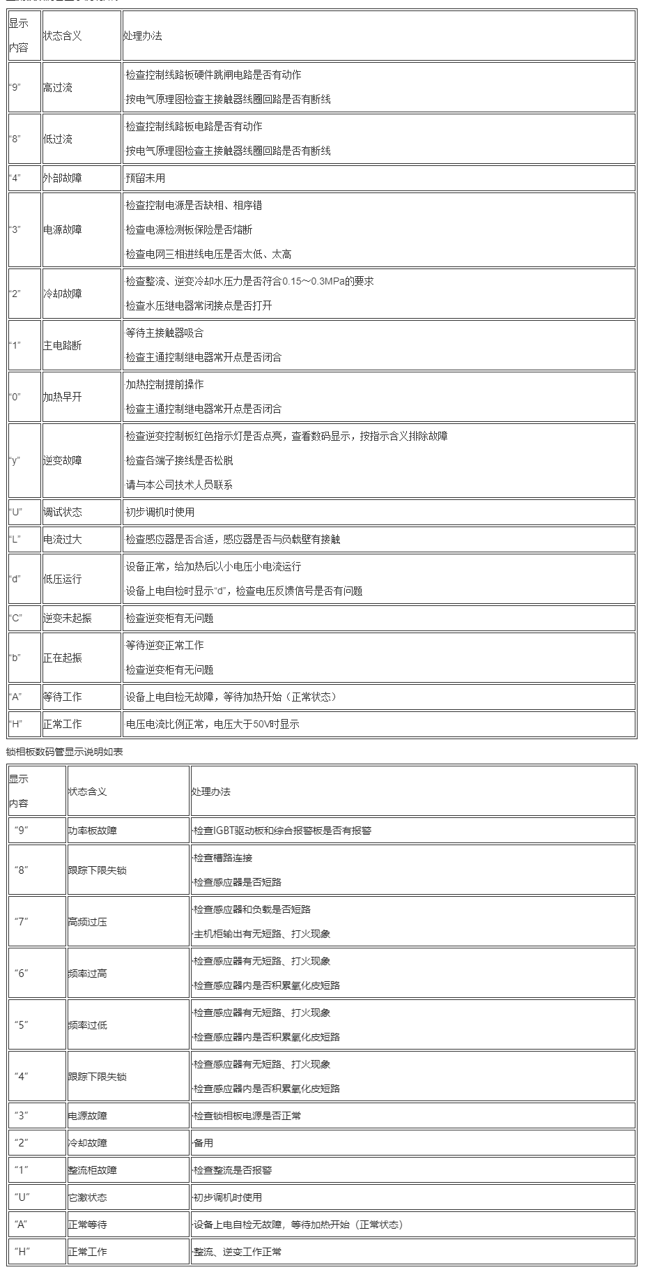
The whole machine is equipped with more than 20 protective measures to improve equipment stability and prevent equipment damage. Alarm information is processed by the control board and sent to the STC microcontroller. Through digital display, maintenance personnel can easily understand the causes of equipment failures and propose solutions.
The display instructions for the rectifier board digital tube are shown in the table

4.3 Low harmonic interference and no pollution to the power grid
Several well matched filtering networks have been designed, and the rectifier operates in a fully conductive state, resulting in minimal harmonic components and a power factor of 0.92 or higher when the solid-state power supply operates at full power.
4.4 Efficiency of over 85%, significant energy savings, and low cooling water usage
Advanced zero voltage and zero current switching technology (ZVZCS technology) eliminates switching losses in power devices.
4.5 High reliability and stable operation
Reasonable process layout and accurate design parameters.
4.6 Allow device to be downgraded for use
In the event of a malfunction and a rush to produce, the equipment can be used at a reduced rate to facilitate user production.
4.7 All control board modules have universality and no need for adjustment

